NeuroScheme User Interface
NeuroScheme UI
After loading a scene the user will be presented with the pane view containing all the entities in a grid visualization (Fig. 1).
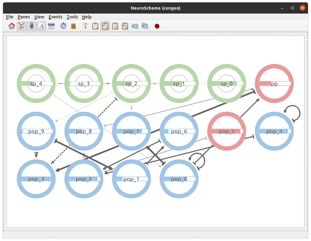
Fig. 1 NeuroScheme user interface.
NeuroScheme Application Toolbar
The application bar presents several icons to perform actions such as sending events, showing or properties of the entities in the scenes (Fig. 2).

Fig. 2 NeuroScheme application tool bar.
From left to right:
Home: Resets the view.
Show connectivity: Shows/Hides the entities relationships.
Show non-hierarchical entities: Shows/Hides non-hierarchical entities.
Show entities name: Shows/Hides the entities’ name.
Clean scene: Removes the scene and clears the view.
Search and filter: Opens the panel to sort or filter entities based on its properties.
Saved selections: Opens the panel to save or restore a selection of entities.
Connect/Disconnect ZeroEQ: Connects/Disconnects the application from ZeroEQ events.
Publish Selection: Publishes the currently selected entities.
Auto publish selection: Enables/Disables the automatic publication of selected entitites.
Send focus event of selected entitites: Sends a focus event on the currently selected entitites.
Automatically send focus event on selection: Enables/Disables the automatic publication of a focus event on the selected entities.
Send focus event of displayed entitites: Sends a focus event on the currently displayed entities.
Automatically send focus event on displayed: Enables/Disables the automatic publication of a focus event on the displayed entities.
Recorder: Shows the recorder configuration dialog and starts recording if the user clicks on the Start button.
Recorder
The recording feature can be activated using the Tools menu or by clicking the Recorder icon in the toolbar. The user will be presented with the recorder configuration dialog (Fig. 3).

Fig. 3 Recorder configuration.
The recorder will generate a Matroska MKV video if the media application ffmpeg is detected and available, if not the generated output will be individual frames. The frames per second of the output can be specified here. The user can choose explicilty which worker (video or frames) to use to generate the output in the advanced configuration dialog (Fig. 4) (enabled using the Advanced recorder options checkbox in the Tools menu).
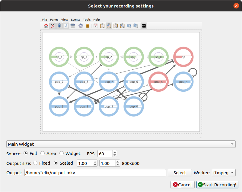
Fig. 4 Recorder advanced configuration dialog.
Using the advanced configuration an area of the application can be selected for recording or an individual widget.
If the output is a video the user can specify the location of the generated file using the Select button. If the output is a sequence of frames the user can specify the destination directory using the Select button in the dialog.
The dimensions of the output are shown and can be modified with the scale options.
While the recorder is working the associated toolbar button will remain down and the icon will change every second with an image of a “Stop” button with REC letters written inside it. The user must click it again to stop the recording. The recorder can also be stopped using the Recorder button in the Tools menu or the keyboard shortcut Ctrl + R.
Note
If the output is a video the filename of the output file will end with “_temporal” while recording. Once the recording has finished it will change to the selected output name in the configuration dialog. The application will warn if the user tries to exit the application while a recording is being made.
Warning
To record a video the system must have ffmpeg installed, preferably with Nvidia hardware acceleration. If ffmpeg is not available in the system only the images worker will be available in the recorder.
Panels
Layout, search and filter panel
The layout, search and filter panel allows the manipulation of the visualization of the selected view pane (Fig. 5).
The layout allows the modification of the representation of the entities. The graph can be configured as:
Grid: Entities placed as a grid, with the options to set the X and Y coordinates padding.
3D: Entities placed in 3D positions.
Scatterplot: Entities placed as a X/Y plot. The options allow the user to specify the properties represented in the X and Y axis.
Circular: Entities placed in a circle, with the option to specify the radius of the representation.
Free: In this mode the entities can be selected by the mouse left button and, once selected, can be moved holding down the shift key and moving the mouse. The entities can be placed anywhere on the pane view.
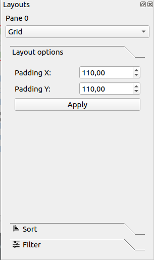
Fig. 5 Layout part of the panel.
Selection panel
The entities can be selected in the view pane by left clicking on them. The selection panel allows the user to store the selection, or to restore or delete an old selection (Fig. 6).
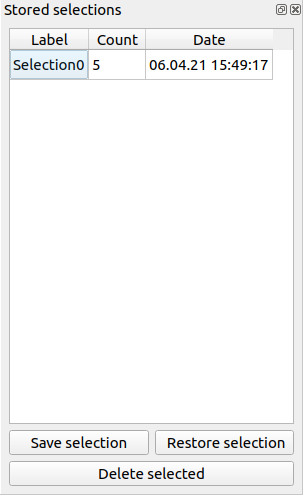
Fig. 6 Selection panel.
When a selection is stored it will ask the user for a name for the selection (Fig. 7).
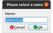
Fig. 7 Selection name dialog.
Entity inspection panel
The entity inspection panel can be opened by using the context menu (right mouse click) on any entity and allows the modification of the properties of the entity. The entity can be deleted from the model using this panel (Fig. 8).
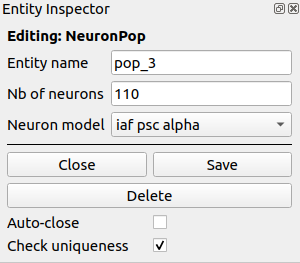
Fig. 8 Entity inspection panel.
Keys and shortcuts
The following actions can be performed by clicking the button, selecting the option at menu bar and pressing the corresponding key combination:
Ctrl + K: Close current view pane.
Ctrl + H: Home.
Ctrl + C: Show/Hide connectivity in the view panes.
Ctrl + I: Show/Hide non-hierarchical entities.
Ctrl + S: Publish selection event.
Ctrl + R: Launch recorder.
Ctrl + Q: Close application.